 Tetrate Service ExpressVersion: Latest
Tetrate Service Express Architecture
Tetrate Service Express (TSE) is built on the foundation of Tetrate's Service Bridge product, with modifications to address AWS use cases and streamline the user experience.
For a detailed explanation of the TSE architecture and data flow, you can refer to the TSB Architecture documentation and related content.
Built on Istio Service Mesh
A Service Mesh is an infrastructure layer that sits between the components of an application and the network. These components are often microservices, but any workload from serverless containers to traditional n-tier applications in VMs or on bare metal can participate in the mesh. Rather than each component communicating directly with each other over the network, proxies intercept that communication.
Tetrate Service Express uses the Istio service mesh. Istio in turn uses the highly-capable Envoy proxy, which is deployed as a 'sidecar proxy' alongside the workloads.
Envoy provides a range of proxy-based capabilities that are used by Istio and Tetrate Service Express:
- Service discovery
- Resiliency: retries, outlier detection, circuit breaking, timeouts, etc.
- Client-side load balancing
- Fine-grained traffic control at L7 (not L4!): route by headers, destination or source, etc.
- Security policy on each request, rather than once per connection
- Authentication, rate limiting, arbitrary policy based on L7 metadata
- Strong (L7) workload identity
- Service-to-service authorization
- Extensibility using WASM Extensions to implement additional functionality
- Metrics, logs, and tracing
The Istio Control Plane
The Istio control plane is responsible for configuring the Envoy sidecar proxies at runtime. As declarative configuration is pushed to the control plane, it transforms those intents into concrete configuration for Envoy at runtime. In effect, the control plane weaves a bunch of individual Envoy proxies into a coherent mesh.
In TSE, each EKS cluster has its own Istio control plane, creating a simple Istio-based mesh per cluster. External services can be onboarded onto any of the Istio meshes. TSE installs, configures and manages the lifecycle of the Istio control plane.
The TSE Control Plane
A bare (no Istio) cluster is onboarded onto TSE. The onboarding process does two things:
- Installs an Istio mesh in the cluster
- Installs a lightweight TSE Control Plane in the cluster
The TSE Control Plane is a lightweight service that configures the Istio mesh on the cluster. This implements the core service mesh features, such as mTLS and routing. The control plane is also responsible for collecting and forwarding application and cluster telemetry to the central Management Plane, and for managing the lifecycle of the Istio mesh using a locally-installed operator.
A TSE Control Plane instance may also be deployed within a VPC to manage traffic to and from non-K8s workloads such as VMs.
The TSE Management Plane
The TSE Management Plane is installed in an EKS cluster. You can reserve a dedicated EKS cluster for the Management Plane, or you can use an existing Workload cluster.
The Management Plane is the place where you interact with TSE, through GUI, CLI, APIs and GitOps interfaces. You can visualize the state of managed clusters, perform upgrades, enforce policy such as runtime controls for the applications deployed in the clusters.
Hidden within the Management Plane is a central Control Plane instance. The central Control Plane takes mesh configuration from the management plane ("configuration intent") and runtime service discovery data from remote clusters ("runtime state"). It resolves this information dynamically to generate optimized Istio configuration and pushes this back to the remote clusters. In this way, TSE facilitates failover and disaster recovery for applications running on and across the clusters.
Understanding the Data Flow
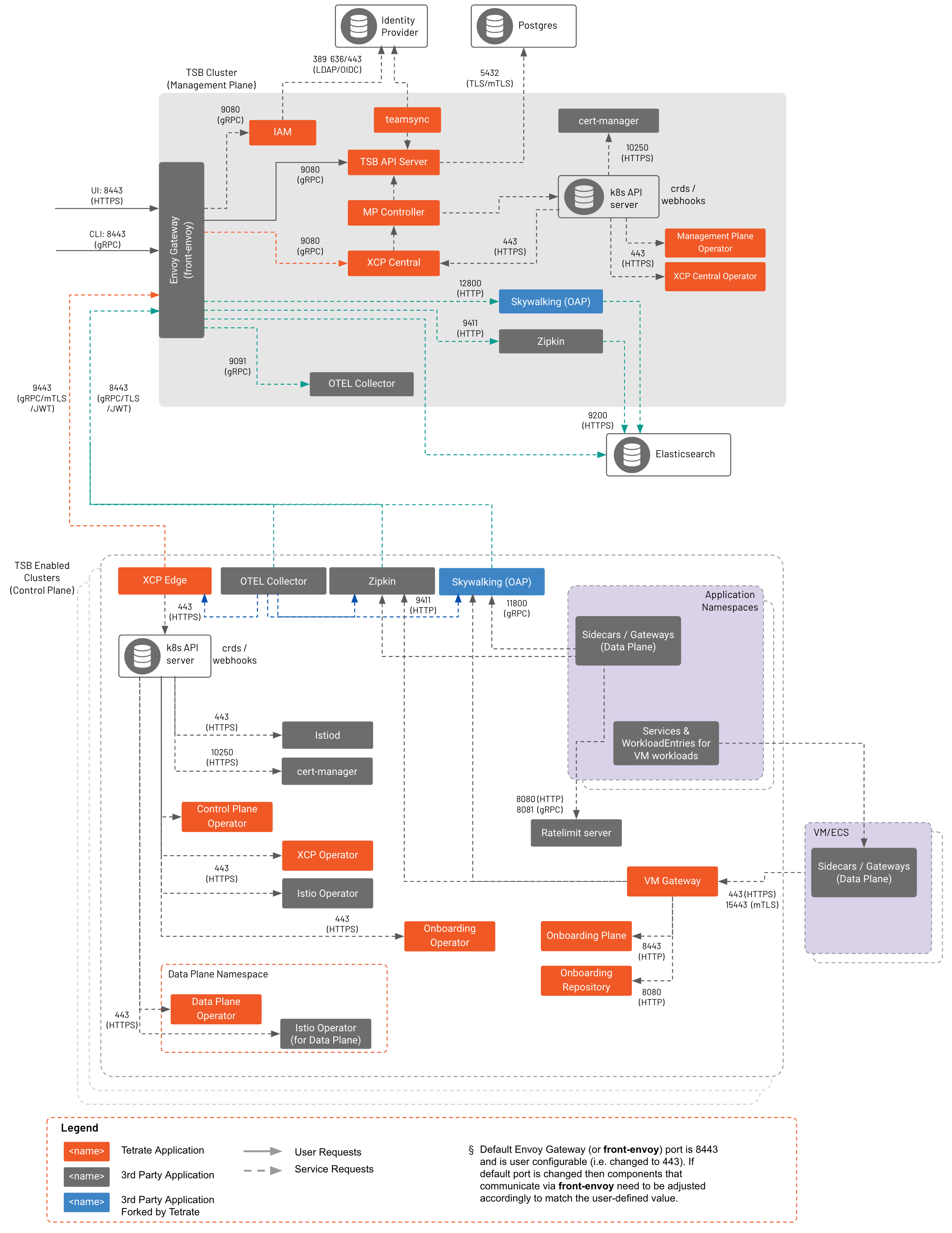 TSE Data Flow TSE Data Flow |
|---|
At a high level, configuration intent flows from from the UI, CLI, and API to the Management Plane, to the central Control Plane, to the remote Control Planes. Each component along the way stores its own snapshot of the configuration, so it can continue to operate in a steady state if it loses its connection up the chain. The Management Plane's configuration store is the source of truth for the entire system.
- The TSE API Server stores the data in its internal postgres datastore
- TSE pushes configuration to the central Control Plane
- The central Control Plane generates Istio configuration and pushes this configuration to Control Plane instances on each remote cluster
- Each remote Control Plane stores incoming objects in their local K8s API server, in the
istio-systemnamespace - The remote Control Plane also subscribes to updates in the
istio-systemnamespace, and publishes native Istio objects when those resources change - Istio processes the configuration objects and pushes them to Envoy instances
In addition, runtime state information, such as service discovery data, is pushed from each remote Control Plane to the central Control plane, and then pushed out to other remote Control Planes as needed:
- The remote Control Plane sends updates to the central Control Plane about service changes
- The central Control Plane then distributes this cluster state update to each of remote Control Planes
- The remote Control Plane manages the configuration it is interested in, storing it in the
xcp-multiclusternamespace as necessary - The remote Control Plane also subscribes to updates in the
xcp-multiclusternamespace, and publishes native Istio objects when those resources change - Istio processes the configuration objects and pushes them to Envoy instances
Interacting with the TSE configuration
You can interact with the TSE configuration via:
- The TSE UI
- gRPC, HTTP/REST, or HTTP-and-YAML APIs
- The
tctlcommand line interface
The UI and tctl both use TSE's gRPC API.
In addition, any changes you make in a local cluster, such as scaling a deployment using kubectl, are reflected in TSE's service registry and may be pushed out to other remote clusters as needed.
Architected for Resiliency and High Availability
The TSE architecture builds around the concept of failure domains. A failure domain is the extent of your infrastructure that is affected when a critical system fails.
Failures can be triggered by a wide range of possible events, from hardware failures, through user configuration errors, to application faults and exploited security vulnerabilities. They can result in infrastructure unavailability, data corruption, failed configuration deployments or resource starvation.
The approach for TSE deployments is to group the sets of co-dependent failure domains into a silo, and then replicate that silo for redundancy and resiliency. The overall reliability of the resulting system depends on how independent we can make the replicas.
Availability Zones and Regions
On AWS, the basic unit of independence is the Availability Zone (AZ). Local outages in one AZ should not affect the operation of neighboring AZs, although this independence cannot always be relied upon.
A higher unit of independence is the Region. A Region is a geographically-separated zone with no interdependencies or shared infrastructure with other Regions.
The choice of AZs and Regions typically becomes a cost-vs-risk analysis. TSE makes it easy to deploy applications across multiple AZs and Regions for redundancy and resiliency.
Logical Failure Domains
Logical failures largely depend on the application architecture, and can be more complex to understand. Applications may depend on many supporting services, such as deployment pipelines, configuration services, databases, loosely-coupled internal and external dependencies, and on how the application is exposed using load balancing, DNS and security tooling.
Modern Cloud-Native Architectures lend themselves well to bundling dependencies with microservices, and to identifying tightly-coupled and loosely-coupled services. Dependencies and tightly-coupled services reside within a failure domain, whereas loosely-coupled services provide an opportunity to span multiple failure domains.
TSE makes it easy to define and manage Ingress and other network services, and to perform high-availability failover for both externally-published and internal-only services.
Keep it Local
One of the easiest ways to create isolated silos without coupled failure domains is to run independent replicas of critical services within each silo.
Tetrate Service Express is architected to use this pattern, and to support applications that use this pattern. TSE runs a standalone instance of the Istio control plane in each compute cluster that runs applications. These instances are loosely coupled, cache state locally, and never need to communicate directly with each other.
The implication is that each cluster, including the local TSE Control Plane, can operate as an isolated island, and a failure in one cluster will not cause failure in others.
This simple model allows TSE to start building more reliable systems by failing over entire silos by rerouting dataplane traffic in the event of a catastrophic failure. In case of a transient failure that results in components being unable to communicate, clusters continue to operate in their current state — with the caveat of not being able to reach the segmented off sections of the ecosystem.
The TSE Management Plane also takes part in failure detection and resolution, and can orchestrate much more fine-grained failover when possible. By managing the local Istio routing, or by reconfiguring the Ingress and other gateways inline to traffic, TSE can perform much more surgical failover, routing traffic to selected services from one cluster to another.